right click for
enlarge


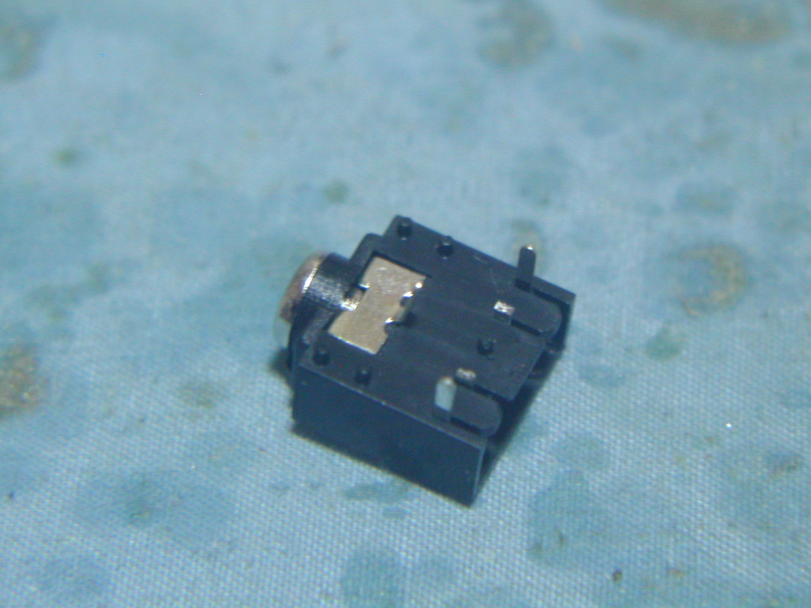
Please short SJ1 GND side.


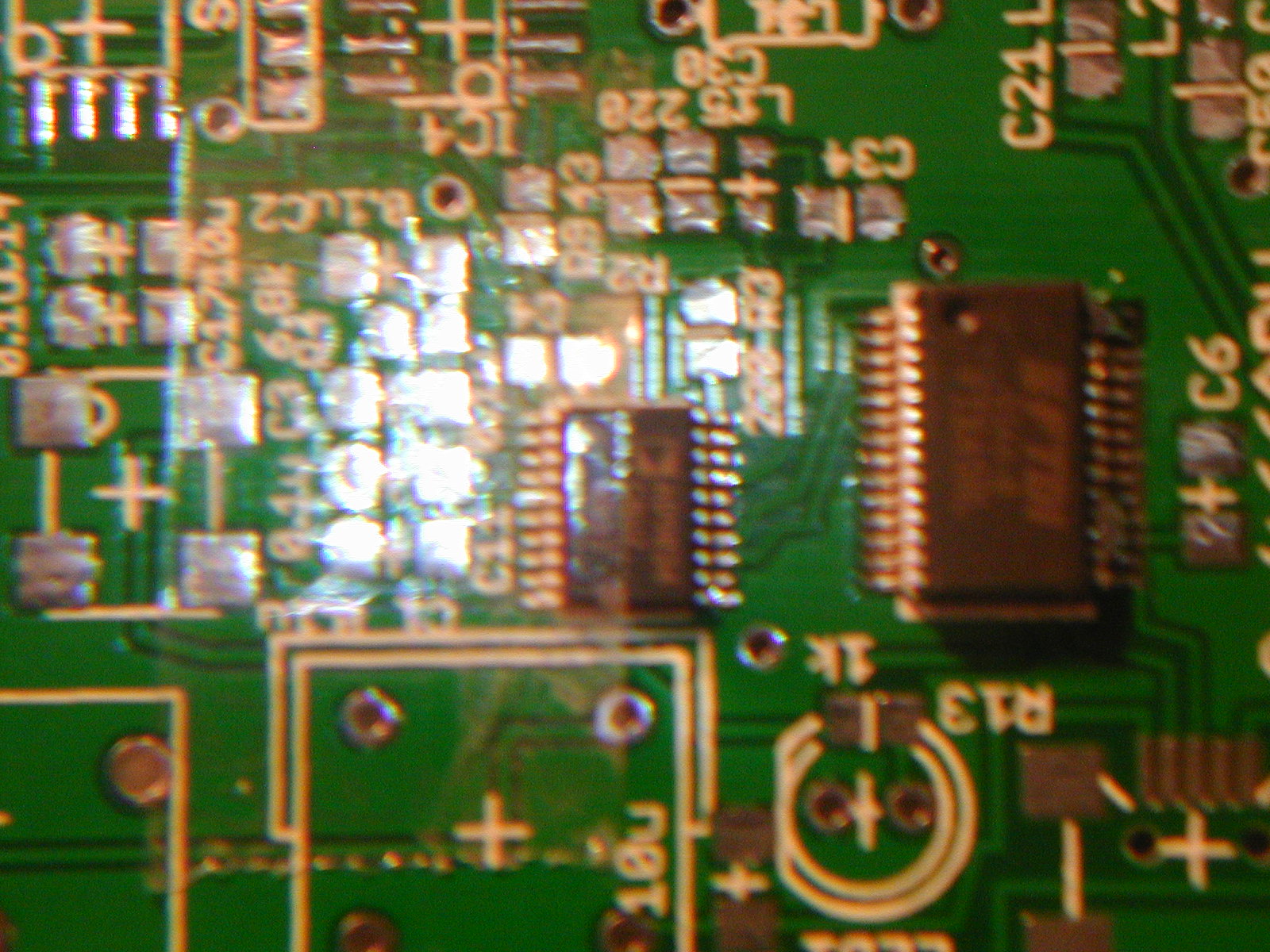
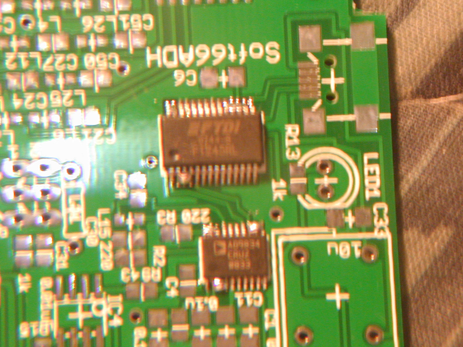
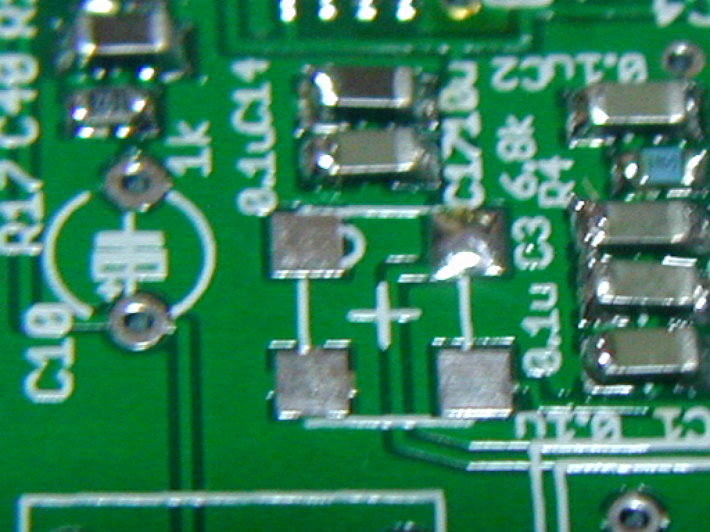
Soft66ADD PCB image
Please note Soft66ADD builders, schematics of Soft66ADD is same as Soft66GPS. Soft66ADD use AD9834 instead of WI125.


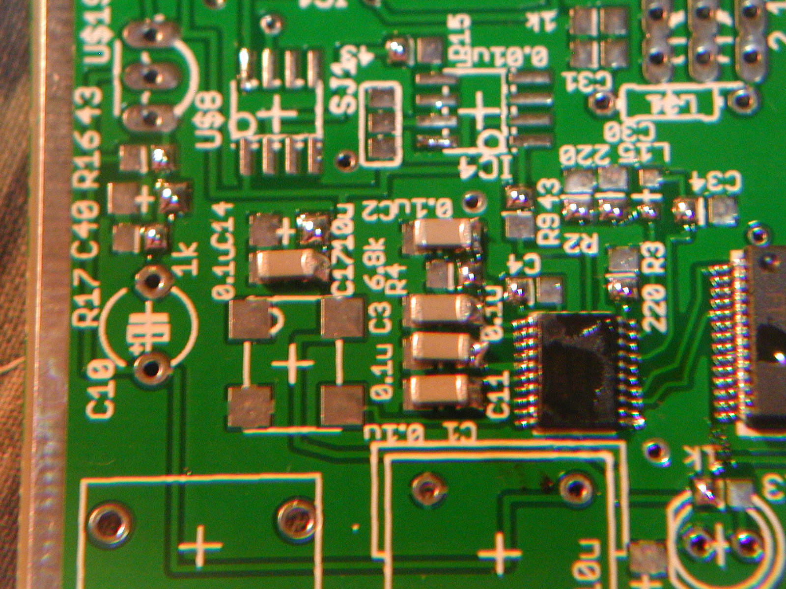
見かけではわからないハンダ不良に、ピンの裏側についたハンダブリッジがあります。 ルーペでよく見るとわかるので、その場合はもう一度ハンダを盛って、裏側のハンダを吸い取ります。
Soft66ADI is a direct conversion receiver. Soft66ADI takes out an AF signal by injecting departure from bureau of the frequency same as the frequency that receive in a mixer. Soft66ADI can get an IQ signal by preparing for the signal which departure from bureau to inject in a mixer was able to drag 90 degrees each.
The signal from an antenna is processed by a band pass filter and a low pass filter. SN74CBT3251 is used for the switch of the filter. Soft66ADI have seven filters and one direct connection circuit.
There is one step amplification of high frequency before a mixer. Soft66ADI use J310. A gain tended to be too big in MW frequency zone, the HF low band, but it is suitable for 21M zone.
Soft66ADI use FET bus switch, SN74CBT3306 for a mixer. Soft66ADI can receive up to the VHF zone.
The low pass filter picking up an AF signal uses OPA2356. It is the slightly luxurious constitution that there is band width more than 200MHz. I set cut-off frequency so that a sound card of 192kHz is usable. Therefore C8,C32 is changed to 220pF.
Soft66ADI use AD9834CURZ of Analog Device for DDS. An oscillation is possible to 37.5MHz by using a clock of 75MHz. AD9834 outputs a square wave by letting inside comparator go through. Soft66ADI get frequency of 4 times in Multipiler IC of the next step, ICS512M. It is reversed 180 degrees signal in next SN65LVDS1 and input it into the Johnson counter of 74LVC74. It can be gotten an IQ signal at 1/2 frequency by paying CLK 180 degrees for the signal which turned over each. Because it was 1/2 at 4 times, Johnson counter, It was able to get an IQ signal of the double frequency of AD9834 in ICS512.
The control of AD9834 goes via USB. Soft66ADI is controlled by FT245RL of FTDI. It is enable to use FT245RL only installing a driver in the PC side. You need no writing firm ware.
Soft66ADI works with bus power of the USB. A lot of noises cannot just use at all the 5V power supply of the USB for a receiver. Therefore I get a power supply through a common mode filter and an active rippled filter.
Commenting on a few about a band pass filter. These BPF are placed from the inside outward, and there is a filter from 1 to 7. A stop filter to deny 7M is in 3rd filter. It is 1uH and 470pF.
In addition, it is filtering it to a tip inductor C23 and C26 with 2,3 doing a low pass.
1:not used
2:05-1.2MHz Low Pass Filter 8uH x2,1800pFx2,3800pF
3:1.2-5.5MHz Low Pass Filter 2.2uHx2,470pFx2,1000pF
4:18.5-30MHz 0.18uHx2,1.2uH,270pFx2,33pF
5:5.5-9.5MHz 1uHx2,2.2uH,470pFx2,180pF
6:9.5-18.6MHz 0.47uHx2,1.5uH,330pFx2,100pF
7:30-70MHz 0.22uHx2,0.22uH,56pFx2,56pF
2、Tools for SMD
I confirm a necessary tool first. Please refer to the preparing one from now on.
30W Solder iron is reccomended, please prepare the thing of the ceramic heater. If you use less watt solder iron, it robbed of heat by GND, and it is hard to solder complete. If you prepare new solder iron, I recommend you buy a thing with the temperature adjustment.
And please prepare for a solder wick the thinnest type.
I reccomend you use flux for BGA type. It may be hard to buy at local shop. Please use flux liquid type.
Precision tweezers, the tip please prepare one sharp thing. When I purchase it in Home Center, it is easy to use it when I buy a good thing of around 1,000 yen. Because there is the thing which the tip does not just match, please warn the cheap tweezers.
A loupe, the magnifier of the cheap shop are recommended.
I use it to stop ADIesive tape, a part. A transparent type is good.
3、Check Parts List
Each part is in a list of parts, the vinyl bag. Please confirm whether there is not the part which is missing from a list of parts first. It is put on the mount with tape, but I pick it up with tweezers, and please take it out. Because there are many cases without the mark in a chip part, please keep on it which is just before to solder.
4、Soldering TSSOP
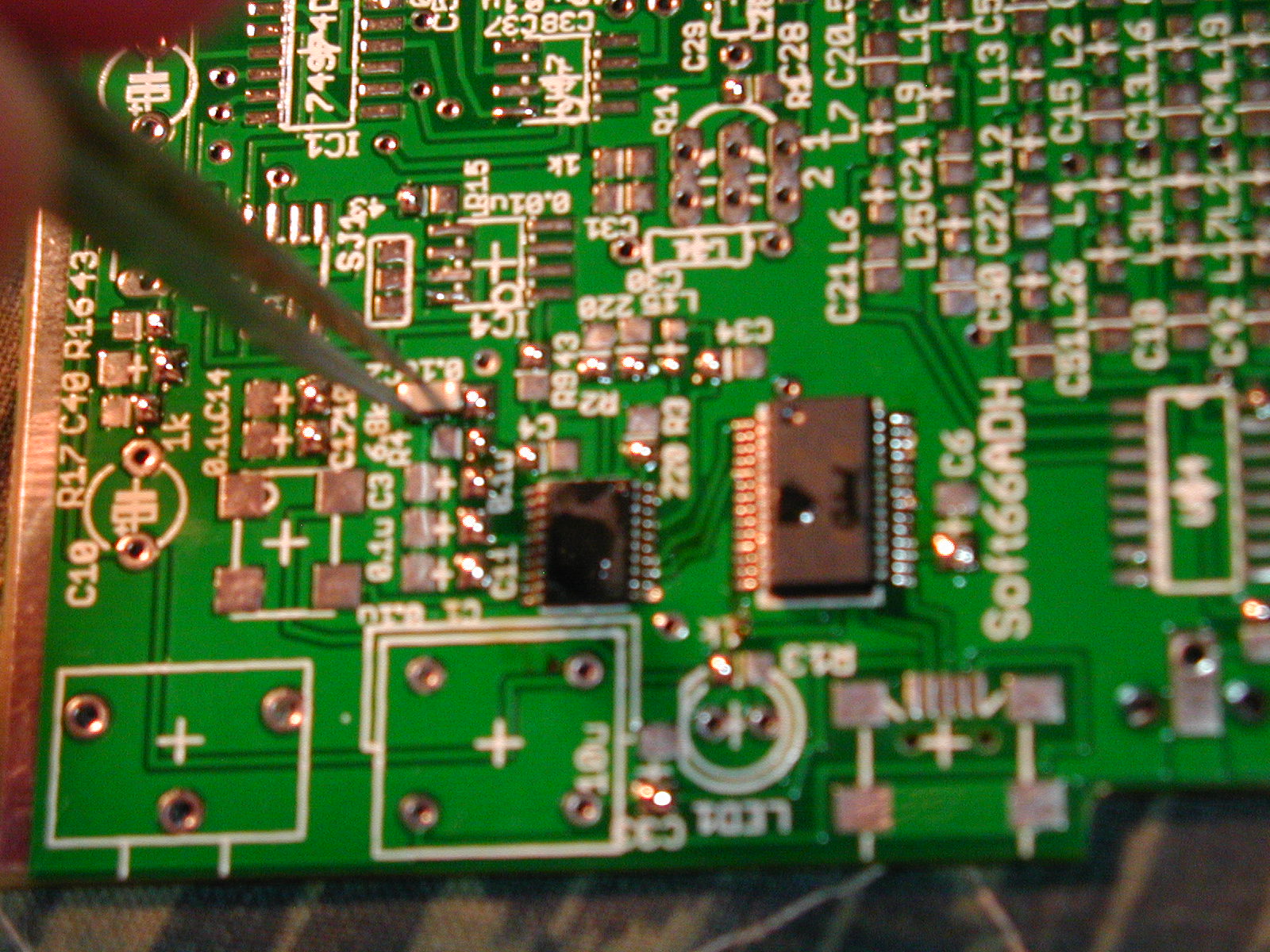
Soldering FT245RL and AD9834CURZ first. I perform the soldering of TSSOP by a method to fix with ADIesive tape. There is another method that used superglue else and hot gun, but the method that used the ADIesive tape is recommended for a beginner.
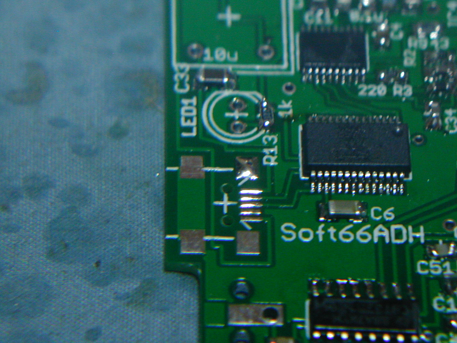
Like the left images, Covering the half of the tip with ADIesive tape and stick it on a print board. It may slip off to some extent then. Inserting tweezers from the gap of the tape, and please match a land with a pin precisely. I perform position laying upon till I understand while confirming it with a loupe.
It carries away solder from the top of the pin if I fix it. Because there is too many it, and there is little|few it, and it is not good, Watch an image, and please regulate it.
Let AD9834 fix with tape. Soldering the both ends of the pin.
Soldering one place of other side. Dissolving solder from this side.
painting flux enough and touch slightly with solder iron and dissolve solder. Please let iron ahead slide on a pin slowly. When solder melts, Comming to follow an iron by surface tension. sliding solder iron few times enough.
Solder comes to stop by the one end of the pin when sliding the iron. Solder is close together by surface tension on an iron.
The current IC is strong for heat. You can work slowly enough.
I think that it is difficult with the weak iron of the capacity.
The unnecessary solder must be removed with solder wick.
Please be careful for completely removing solder, because a pin comes off. When you take off solder wick, please tear it off while heating it in iron ahead. A pin loosens when you lift it forcibly.
Like an image of the finish, the state that solder is delicately left around a pin is an ideal. Because there is the case that a bridge can take by surface tension when I paint with a flux once again and can warm up with an iron even if a solder bridge is done between pins to some extent, please try it.


